Solutions of Exercise 4.2#

Fig. 26 Block diagram of the DC-servomotor.#
In Fig. 26 the block diagram of a DC-servomotor is illustrated.
In this system, the input voltage \(u\) first goes through a isolated DC-DC convert[1], which applies the desired voltage \(u\) to the motor. This converter is modeled by the first-order transfer function with time constant \(T=10\) ms.
The voltage is then applied to the motor, described by a second order transfer function with gain \(k_m=10\), electrical time constant \(T_2 =25\) ms, and mechanical time constant \(T_1 = 50\) ms.
The servomotor is first tested with \(F(s) = 1\), but the closed-loop turns out to be too slow.
Find \(F(s) = K\) so thatthe closed-loop is twice as fast as for \(F(s)=1\).
Then, find \(K\) so that the following accuracy requirements are sastisfied:
When \(\theta_{ref}(t) = \textrm{step}(t)\), at steady state \(\lvert \theta - \theta_{ref} \lvert \leq 0.001\)
When \(\theta_{ref}(t) = 10 \cdot \textrm{ramp}(t)\), at steady state \(\lvert \theta(t) - \theta_{ref}(t) \lvert \leq 0.01\)
(Extra!) Assume that the motor current can be measured. With the help of MATLAB, design a cascade control scheme for \(G_2(s) = \frac{Z(s)}{U(s)} = \frac{1}{(1+sT)(1+sT_2)}\) and \(G_1(s) = \frac{Y(s)}{Z(s)} = \frac{10}{s(1+sT_1)}\), so that the phase margin is at least \(60^\circ\), and the bandwidth of the servomotr is at least \(100\) rad/s.
Solution#
Question 1#
First of all, let’s compute the bandwith for \(F(s) = K = 1\). The open loop transfer function is defined as
while the closed-loop transfer function is
Finding \(\omega_B\) such that \(\lvert G_c(i \omega_B) \lvert = \frac{1}{\sqrt{2}}\) is impractical because of its high order.
Instead, we can sketch the Bode plot of \(G_o(s)\) and compute the critical frequency \(\omega_c \approx \omega_B\).
s = tf('s');
G = 10 / (s * (1 + 0.01*s) * (1 + 0.025*s) * (1 + 0.05*s));
figure;
bode(G, {1, 1000});
grid on;
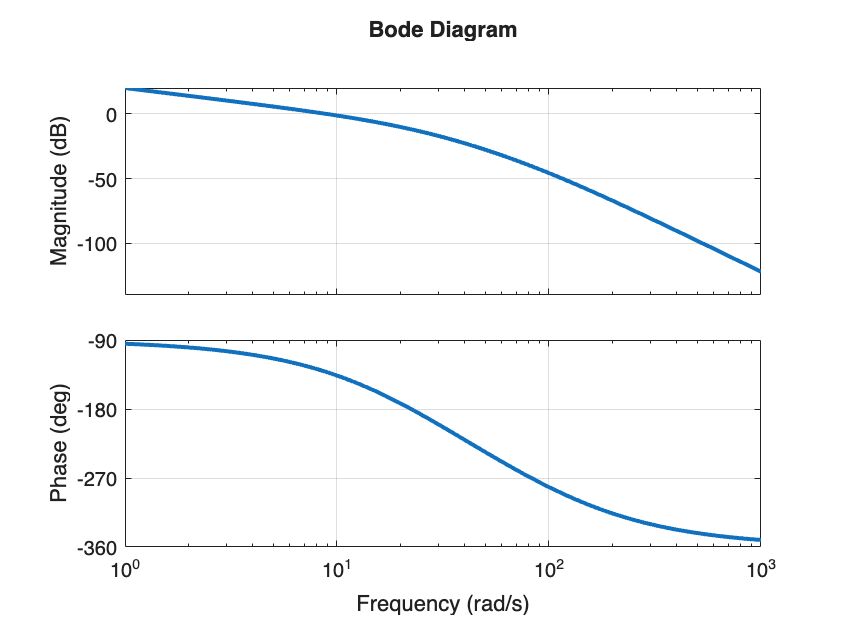
The bandwidth for \(K=1\) is approximately \(9\) rad/s.
This means we are required to find \(K\) such that the critical frequency is \(18\) rad/s. Looking at the Bode plot of \(G(s)\), we can see that \(\lvert G(i 18) \lvert_{\text{dB}} \approx -8 \) dB.
mag_at_18 =  mag2db(abs(freqresp(G, 18)));
disp(sprintf('Magnitude at 18 rad/s: %.1f dB', mag_at_18));
Magnitude at 18 rad/s: -8.6 dB
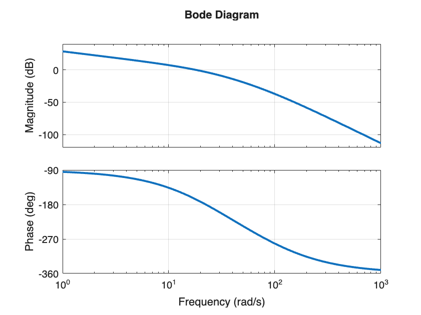
Therefore, taking \(K = 8.6 \text{ dB } = 2.7\) we get an open-loop transfer function with critical frequency \(\omega_c = 18\) rad/s
Go = 2.7 * G;
figure;
bode(Go, {1, 1000});
grid on;
Note
Remember that \(\omega_B\) is not exactly equal to the critical frequency \(\omega_c\). It is just a useful approximation!
G_c = G / (1 + G); % Closed looop transfer function for K=1
[mag, ~, w] = bode(G_c, {1, 1000});
w_b = w(find(mag > 1/sqrt(2), 1, 'last'));
disp(sprintf('Closed-loop bandwidth for K=1 is %.2f rad/s, while the critical frequency is %.0f rad/s', w_b, 9));

G_c = Go / (1 + Go); % Closed looop transfer function for K=2.7
[mag, ~, w] = bode(G_c, {1, 1000});
w_b = w(find(mag > 1/sqrt(2), 1, 'last'));
disp(sprintf('Closed-loop bandwidth for K=2.7 is %.2f rad/s, while the critical frequency is %.0f rad/s', w_b, 18));
Closed-loop bandwidth for K=1 is 14.42 rad/s, while the critical frequency is 9 rad/s
Closed-loop bandwidth for K=2.7 is 28.45 rad/s, while the critical frequency is 18 rad/s
Question 2#
Consider the open-loop transfer function (12) and the closed-loop transfer function (13) for a generic gain \(K\).
We start by analyzing for what values of \(K\) the closed-loop remains stable. For this, we can use root locus.
figure;
rlocus(G); hold on; % Plot the root locus

% Plot the closed-loop poles for specific values of K
K_points = [2.7, 3.9];
for k=K_points
    Gok = k * G;
    [num, den] = tfdata(Gok, "vector");
    poles = roots(num + den);
    p = plot(real(poles), imag(poles), 's', 'MarkerSize', 10, 'MarkerFaceColor', 'auto', 'DisplayName', sprintf('K=%.2f', k));
    set(p, 'markerfacecolor', get(p, 'color'));
end
legend('Location', 'northwest'); hold off;
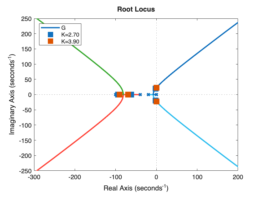
The closed-loop is stable for \(0 < K < 3.9\).
Error for step references#
For step references, i.e. \(\theta_{ref}(t) = \textrm{step}(t)\), the steady-state tracking error is exactly \(0\), provided that the closed loop is stable (\(0 < K < 3.9\)). In fact, the type of \(G_o(s)\) is \(g=1\), because \(G_o(s)\) has exactly one pole in \(s=0\).
Error for ramp references#
When it comes to \(\theta_{ref}(t) = 10 \cdot \textrm{ramp}(t)\), we can apply the Final Value Theorem
In order to get the desired \(1\%\) accuracy we would need \(K> 100\), which unfortunately breaks the closed-loop stability assumption of the Final Value Theorem!
Question 3#
The solution will be provided over the next few weeks.
Hints:
Use PD controllers for both the outer and the inner control loop.
Use the function
margin(Go)to evaluate the phase and gain margin given the open loop transfer functionGoRemember that the bandwidth of the inner loop must be at least \(10\times\) larger than that of the outer loop.