Exercise 4.2#
Fig. 12 Block diagram of the electric car#
The cruise controller of an electric car works by adjusting the voltage applied to the electric motor to regulate the velocity, making sure it is as close as possible to the speed setpoint coming from the driver. The system has the following dynamics:
Electric Dynamics (Voltage \(\to\) Current): \(G_2(s) = \frac{90}{s + 100}\)
Mechanical Dynamics (Current \(\to\) Speed): \(G_1(s) = \frac{5}{s + 0.2}\)
The block diagram of the car is shown in Fig. 12. Both the motor current and the car velocity are measured, respectively with an Hall-effect sensor and a speedometer.
Sketch the block diagram of the system when a cascade control scheme is used. What are the control variable, the intermediate signal that is fed back in the internal loop, and the output?
We start designing the cascade control scheme by the inner controller. Assume that we use a proportional controller \(F_i(s) = K_2\). Design \(K_2\) so that the bandwidth of the inner loop is at least \(50\) rad/s and the steady-state error of this internal loop is no larger than \(1\%\).
We now design the controller for the outer loop as a proportional controller \(F(s) = K_1\). Choose \(K_1\) so that the bandwidth of the closed-loop is at least \(1\) rad/s.
Compute the steady-state output tracking error of the closed-loop. How can you modify the scheme so that the steady-state error is exactly zero?
Solution#
Question 1#
The cascade control scheme is implemented by closing the inner loop with the current measurement, and the outer loop with the speed measurement. The resulting block diagram is depicted below.
Fig. 13 Cascade control scheme.#
Question 2#
The inner control loop is characterized by the open-loop transfer function \(G_{o2}(s) = F_i(s) \cdot G_2(s) = \frac{90 K_2}{s + 100}\), and by the closed-loop transfer function
This closed-loop is stable if \(100 + 90 K_2 > 0\), i.e. \(K > - \frac{10}{9}\). Therefore, any \(K_2 > 0\) ensures closed-loop stability.
According to the Final Value Theorem, at steady state the output tracking error of \(G_{c2}(s)\) is
The static error is less than \(1\%\) if \(\frac{90 K_2}{100 + 90 K_2} \geq 1 - 0.01\), that is
As for the bandwidth requirement, \(\omega_B\) is defined as the frequency where \(\lvert G_{c2}(i \omega_B) \lvert = \frac{\lvert G_{c2}(0) \lvert}{\sqrt{2}}\). Under the reasonable assumption[1] that \(\lvert G_{c2}(0) \lvert \approx 1\), we can consider the simpler definition \(\lvert G_{c2}(i \omega_B) \lvert = \frac{1}{\sqrt{2}}\), or equivalently \(\lvert G_{c2}(i \omega_B) \lvert_{\text{dB}} = -3\) dB.
Therefore, we need to solve \(\lvert G_{c2}(i 50) \lvert = \frac{1}{\sqrt{2}}\) for \(K_2\)
Since both sides are positive for any \(K_2 > 0\), we can square them and re-arrange the equations as follows
We can divide both sides by \(100\) and solve by \(K_2\)
Any \(K_2 > 2.8\) guarantees a bandwidth larger than \(50\) rad/s.
Solution: Both requirements are satisfied when \(K \geq 110\). Let’s check this with MATLAB.
s = tf('s');
G_2 = 90 / (s + 100);
K_2 = 110;
G_o2 = K_2 * G_2;           % Open-loop transfer function
G_c2 = G_o2 / (1 + G_o2);   % Closed-loop transfer function
Starting MATLAB ...
Executing ...
figure;
bode(G_c2); grid on;

[mag, phase, wout] = bode(G_c2); % Get the magnitude, phase, and frequency data
w_b = wout(find(mag < 1 / sqrt(2), 1, 'first'));
disp(['Bandwidth: ', num2str(w_b), ' rad/s'])
disp(['Static gain: ', num2str(dcgain(G_c2))])
Bandwidth: 10000 rad/s
Static gain: 0.99
figure;
step(G_c2, 1e-3); grid on;

if exist('stepinfo')
    disp('Step response information: '); disp(stepinfo(G_c2))
end
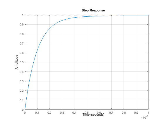
Step response information:
         RiseTime: 2.1970e-04
    TransientTime: 3.9121e-04
     SettlingTime: 3.9121e-04
      SettlingMin: 0.8910
      SettlingMax: 0.9893
        Overshoot: 0
       Undershoot: 0
             Peak: 0.9893
         PeakTime: 7.3222e-04
Question 3#
At this stage, we approximate \(G_{c2}(s) \approx 1\). Therefore, the open-loop transfer function of the outer loop is
The resulting closed-loop is
The values of \(K_1\) for which the bandwidth requirement is satisfied can be found in two ways: from the Bode plot of \(G_{o1}(s)\), or analytically.
From Bode plot#
% Check if the `asymptotic_bode` function is available, otherwise download it
if ~exist('asymptotic_bode')
    urlwrite('https://raw.githubusercontent.com/bonassifabio/1RT485/refs/heads/main/book/res/matlab/asymptotic_bode.m', 'asymptotic_bode.m');
end

G_1 = 5 / (s + 0.2);
figure;
asymptotic_bode(G_1); grid on;
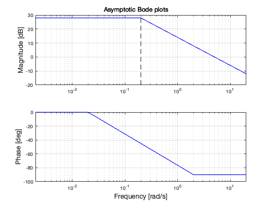
Let’s recall that the bandwitdh \(\omega_B\) can roughly be approximated as the critical frequency \(\omega_c\) where \(\lvert G_{o1}(i \omega) \lvert_{\text{dB}} = 0\) dB. Then, the magnitude of \(G_1(s)\) at the target critical frequency \(\omega_c = 1\) rad/s is \(\lvert G_1(i 1) \lvert_{\text{dB}} \simeq 15\) dB. Therefore, since \(\lvert G_{o1}(i \omega) \lvert_{\text{dB}} = \lvert G_{1}(i \omega) \lvert_{\text{dB}} + \lvert K_1 \lvert_{\text{dB}}\), the bandwidth requirement is satisfied by \(K_1 > - 15\) dB. That is, \(K_1 > 10^{\frac{-15}{20}} \simeq 0.18\).
Analytical solution#
The bandwidth of \(G_{c1}(s)\) is defined as the value of \(\omega\) such that
We therefore solve \(\lvert G_{c1}(i 1) \lvert = \frac{1}{\sqrt{2}}\) for \(K_1\)
Because both sides are positive for any \(K_1 > 0\), we can square them. With some manipulation we get
K_1 = 0.25;
G_o1 = K_1 * G_1;
G_c1 = G_o1 / (1 + G_o1);

figure;
bode(G_c1); grid on;
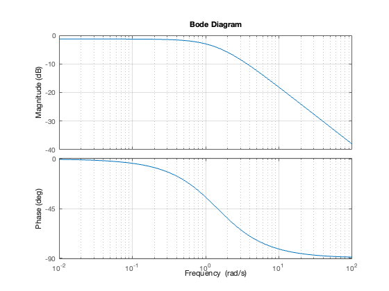
[mag, phase, wout] = bode(G_c1);  % Get the magnitude, phase, and frequency data
w_b = wout(find(mag < 1 / sqrt(2), 1, 'first'));
disp(['Bandwidth: ', num2str(w_b), ' rad/s'])
disp(['Static gain: ', num2str(dcgain(G_c1))])
Bandwidth: 1.0848 rad/s
Static gain: 0.86207
Question 4#
Recalling (5), the overall closed-loop transfer function is
Picking \(K_2 = 110\) and \(K_1 = 0.25\),
The steady-state error for a step reference is
\(e_\infty = \lim_{s \to 0} s \big[ 1 - G_c(s) \big] \frac{1}{s} = \frac{2000}{14375} \simeq 14 \%\)
Gc = (K_1 * G_c2 * G_1) / (1 + K_1 * G_c2 * G_1);
disp(['Steady state error: ', num2str((1 - dcgain(Gc))*100), '%'])
Steady state error: 13.913%
This means that if the velocity target is \(60\) km/h, the cruise control will reach \(51\) km/h!
Question 4#
To achieve zero steady-state error, it is enough to use a PI controller.
The new open-loop transfer function (assuming \(G_{c2}(s) = 1\) for the sake of simplicity) is
Since \(G_{o1}(s)\) is of type \(g=1\) (i.e., it has \(g=1\) poles in the origin), the steady-state error for step references is exactly \(0\).
How to design the PI controller?#
An easy design choice is to use the zero of the PI controller to cancel the pole of the system.
In this way, \(G_{o1}(s)\) becomes
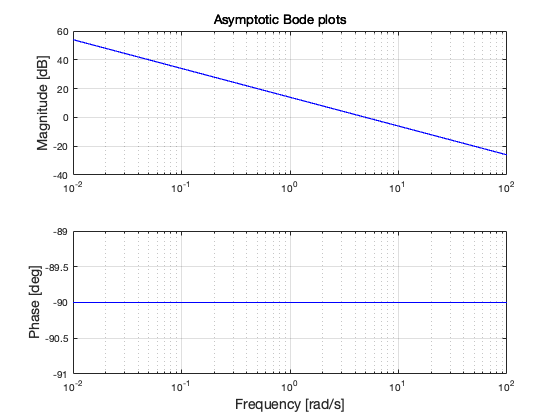
The proportional gain \(K_{1P}\) is designed so that the critical frequency \(\omega_c\) is larger than the desired bandwidth \(1\) rad/s. To this end, we can proceed in the same way as in the section From Bode plot.
figure;
asymptotic_bode(5 / s); grid on;
mag_at_1 = mag2db(abs(freqresp(5 / s, 1)));
disp(['Magnitude at 1 rad/s: ', num2str(mag_at_1), ' dB'])
Magnitude at 1 rad/s: 13.9794 dB
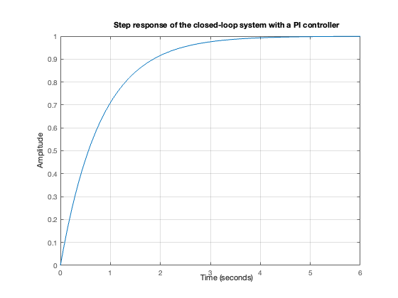
Solution: \(K_{1P} > - 14\) dB guarantees the desired bandwidth. For example, \(K_{1P} = 0.25\) and \(K_{1I} = 0.2 \cdot K_{1P} = 0.05\).
Let’s just check this solution with MATLAB.
F_PI = 0.25 + 0.05 / s;

Gc_new = (F_PI * G_c2 * G_1) / (1 + F_PI * G_c2 * G_1);
disp(['Steady state error: ', num2str((1 - dcgain(Gc_new))*100), '%'])
Steady state error: 0%
figure;
step(Gc_new, 6); grid on;
title('Step response of the closed-loop system with a PI controller')
if exist('stepinfo')
    disp('Step response information: '); disp(stepinfo(Gc_new))
end
Step response information:
         RiseTime: 1.7749
    TransientTime: 3.1618
     SettlingTime: 3.1618
      SettlingMin: 0.9088
      SettlingMax: 1.0000
        Overshoot: 0
       Undershoot: 0
             Peak: 1.0000
         PeakTime: 8.8557
